Induction Motor Rewinding Calculation
- Induction Motor Rewinding Calculation
- Induction Motor Rewinding Calculations
- Induction Motor Winding Calculation
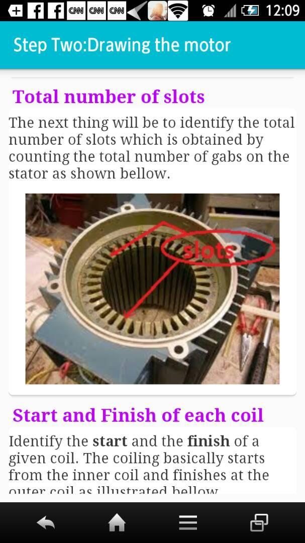
Repulsion Start Induction Motor. Repulsion Induction Motor. Plain Repulsion Motor. The Stator of the PlainRepulsion Motor is the same as Single Phase Induction Motor. The stator winding has distributed concentric winding for two or more number of poles. There is only one winding in the stator. Induction motors employ an armature that rotates within a fixed stator, with a small air gap between the two. A typical motor stator is shown below. Typical induction motor stator It consists of a core of stacked, insulated, iron laminations, with windings of insulated copper wire. By Mike Switzer, Product Line Manager - Motors. During the life span of every 3 phase electric AC motor, the stator windings will need to be rewound. The timing of a needed motor rewinding will vary according to the application and environment. Mechanical failures could also cause the rotor to fail unexpectedly, calling for a rewind. If the copper loss is too high, select a winding distribution that is more efficient. In order to calculate the copper loss, you need to know the full-load current. To calculate that, you need all of the design characteristics of the motor including stator and rotor resistance and leakage reactance, magnetizing reactance and iron loss.

An electrical motor is one kind of machine which is used to change the energy from electrical to mechanical. Most of the motors work on the principle of interaction among the electric current as well as the magnetic field within a wire winding. This can generate force in the form of shaft rotation. These motors can be powered with DC or AC sources. The DC sources are batteries whereas the AC sources are inverters, power grids, generators. A generator is mechanically similar to the motor but works in the reverse direction by converting the energy from mechanical to electrical. An electric motor can be built with the rotor, stator, air gap, windings, bearings, & commutator. The classification of motors can be done with considerations like the type of power source, construction, motion output type, and applications. This article discusses what is a motor winding, types, and its calculation.
What is Motor Winding?
The electric motor winding definition is, windings in electric motors are wires that are placed within coils, generally enclosed around a coated flexible iron magnetic core to shape magnetic poles while strengthened with the current. Electric machines are available in two fundamental magnet field pole configurations namely salient pole as well as a non-salient pole. The motor winding diagram is shown below.
In the salient pole configuration machine, the magnetic field pole can be generated produced with a winding wound approximately under the pole face. In the non-salient pole configuration, the winding can be dispersed within slots of pole face. A shaded pole motor includes a winding which is placed around the pole part that holds up the magnetic field phase. Some kinds of motors include conductors with thicker metal like sheets of metal otherwise bars generally copper, otherwise aluminum. Generally, these are power-driven with electromagnetic induction.

Types of Motor Windings
The motor winding types are two types which include the following.
- Stator Winding
- Rotor winding
Based on the motor winding connection, armature windings are classified into two types which include the following.
- Lap winding
- Wave Winding
Stator Winding
The slot on stator core of the three-phase motor winding carries stator winding. This winding can be supplied with 3-phase AC supply. The motor winding in three-phase which is connected in star or delta form based on the type of starting method used.


The motor like squirrel cage can be frequently on track by the star to delta stator & thus the stator of the motor can be connected in delta. The slip ring 3-phase induction motor is in progress by including resistances, thus the slip ring induction motor’s stator winding can be associated in star otherwise delta form.
Whenever the stator winding is energized by 3-phase ac supply, then it generates a rotating magnetic field (RMF).
Rotor Winding
In a motor, the rotating part is known as the rotor. The rotor includes the rotor winding as well as rotor core. The rotor winding is energized by the DC supply. The rotor can be classified into two types namely the phase wound and the squirrel cage.
The squirrel cage rotor’s core is made up of cylindrical iron core which has a curved slot over the external surface on which the aluminum or copper conductors are located. These are short-circuited at the endings using the copper or aluminum rings.
The electromagnetic induction is the occurrence wherein the electromagnetic force is induced within the conductor which carries the conductor due to the variable magnetic field. When the current stimulates in the rotor then it causes the rotor to move.
Lap Winding
Lap winding is the one kind of armature winding. The conductor connection can be done where the lanes and poles are similarly connected. The final part of each armature coil is associated with the commutator. The number of brushes within winding is the same as the number of parallel lanes. These are divided equally into two polarity windings like positive & negative. The lap winding applications mainly involve in high current and low voltage machines. These windings are categorized into three type’s namely simplex, duplex and triplex type winding.
Wave Winding
Wave winding includes parallel lanes among the two brushed like positive & negative. The primary armature coil’s end part can be associated with the starting part of the next armature coil commutator part with some distance. The conductors in this type of winding can be connected with two parallel lanes in a machine pole. The number of parallel ports can be equal in the direction of the number of brushes, which is used for high-voltage, and low-current machines. Please refer to the link to know more about Lap Winding & Wave Winding.
Motor Winding Calculation
The motor winding wire calculation can be done using an ohmmeter. Connect the positive terminal of the multimeter which is in red color to the positive terminal of the windings of the motor. Similarly, connect the negative terminal which is in black color to the negative terminal of the windings of the motor. The reading of the motor winding machine can be displayed on the multimeter screen that is resistance in ohms.
Induction Motor Rewinding Calculation
With the help of Ohm meter, detach the power supply from the motor. Place meter on ohms and generally the range can be expected from 3 to 2 ohms. If we observe the reading like zero, and a short among phases occurs. Generally, if it is open then it will be above 2K ohms or infinite.
Induction Motor Rewinding Calculations

Induction Motor Winding Calculation
Thus, this is all about an overview of the motor winding theory. From the above information finally, we can conclude that windings are made with copper wires which are wound around a core to make or obtain electromagnetic energy. The wire utilized within the windings should be protected. But in some cases, we can see the windings like bare copper but it’s simply coated with enamel. The most commonly used material for winding is copper. Aluminum can also be used but it should be thicker to hold a similar load securely. The copper winding allows for a tiny sized motor.
These motor windings are very important components within an electrical machine. It includes a set of coils in the slots as well as consistently spaced in the region of the winding’s margin. Here is a question for you, what is cooler motor winding?